SDUCT
Help file
Title: SDUCT User Guide
Date: December 21, 2017
Hi, Thank you discovering SDUCT and welcome to the help file.
You must find all information about this product in this document.
Contents
SYMBOLOGY USED IN THIS HELP FILE
INTRODUCTION
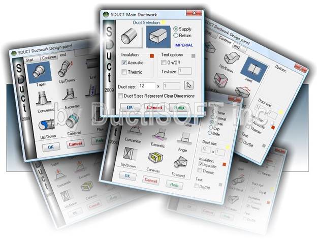
SDUCT R19 allows you to quickly draw double line ductwork, using an intuitive graphical interface. The goal of this program is to decrease the drafting time while at the same time making your drawings look consistent.
SYMBOLOGY USED IN THIS HELP FILE
Text that appears in BLUE in this help file indicates that this is text that should be typed at the command line in AutoCAD.
INSTALLATION
Double click the exe to begin the installation of SDUCT, please note that AutoCAD should be closed when installing SDUCT for the first time. After the installation is completed, Start a CAD session and Load via the _Appload command the SDUCT.vlx file located at the installation path. If you are using AutoCAD, a ribbon menu must be present in the Add-ins tab.
Note: SDUCT work with ObjectDCL technologie. You must download and install ObjectDCL to use this application. For more information about ObjectDCL, please visit the website at: http://www.ObjectDCL.com
CONSISTENT BUTTONS
There are three buttons that behave the same no matter which dialog screen is open, these are:
- OK
- Accepts all settings on the screen you are currently on and goes on to the next step when applicable.
- Cancel
- Escapes from whatever dialog you are currently on.
- Help
- Brings up this help file.
CONFIGURATION
After installing SDUCT, the first step is to configure it for your standards, to do so type SDCONFIG command. After doing so, the following dialog box will appear:
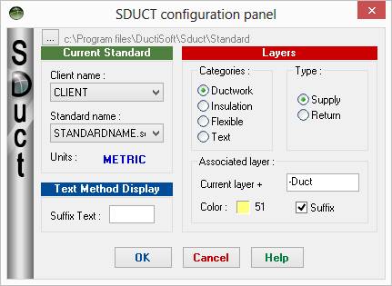
The C:\Program Files\DuctiSOFT\Sduct\Standard indicates the folder that the standards are located in, you can modify this for various clients or to standardize your office by using a shared network drive location.
CLIENT NAME
This is where you can specify a client name, so that each client can have different standards, even in one file or folder.
STANDARD NAME
This is where you can specify a standard name, so that if a particular client has more than one standard you can adjust for that as well.
Units indicates if this standard is based on Imperial (U.S.) units or Metric units.
The Text Method Display is where you can set any suffix that you need to add on to text, such as the “ symbol or mm.
LAYERS
You can set the layers that you wish to use for supply and return for each type of Categories, if the suffix box is checked, then whatever is in the text box will just be added to the current layer. Color allows you to set the color of each layer. SDUCT will create the layer if not exist.
USING SDUCT
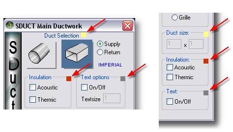
To begin using SDUCT, type SDUCT at the command prompt, after doing this you will see the following dialog box:
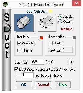
DUCT SELECTION
In this section you choose which type of duct you are going to draw, click on the appropriate button to highlight it, the one on the left indicates that you are going to draw round ductwork, the one on the right indicates that you are going to draw rectangular ductwork.
If the radio button next to Supply is filled in, you will be drawing supply ductwork, if the radio button next to Return is filled in you will be drawing return ductwork.
Underneath the radio button it indicates if you are currently drawing Imperial or metric ductwork.
INSULATION
If the box next Acoustic has a check mark in it, the ductwork that you are going to draw will have Acoustic (internal) insulation.
If the box next Thermic has a check mark in it, the ductwork that you are going to draw will have Thermic (external) insulation.
TEXT OPTIONS
If there is a checkmark in the box next to On/Off, it indicates that SDUCT will draw text with your ductwork.
Textsize is where you can set the height of your text that sduct draws.
DUCT SIZE
Enter the size of the duct that you wish to draw or click the arrow to graphically specify the duct size.
If there is a checkmark next to Duct Sizes Represent Clear Dimensions and you are drawing Acoustic (internal) Insulation, the duct size specified will indicate the clear space inside of the insulation, making the duct larger as needed. NOTE: In future releases this option may be moved to the SDCONFIG dialog box.
ROUND DUCTWORK
When you begin to draw round ductwork you will see the following dialog box:
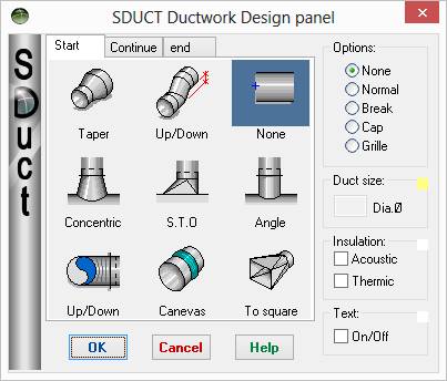
TAPER
This option allows you to transition from one ductsize to another, when you select this option the DuctSize box will become available so that you can indicate the new ductsize.
UP/DOWN (TOP MIDDLE)
This option allows you to indicate that there is a rise or drop in the duct elevation at this point, this does not show duct risers.
NONE
This option allows you start ductwork with various options:
· None
o This option allows you start with nothing at the end of a duct, this is very handy if you already have a duct riser that you just need to come off of the side of for example.
· Normal
o This option will show a line closing of the duct.
· Break
o This option adds in a breakline, so that you can show that the duct doesn’t stop but continues on. This is handy when you need to show that a duct goes under a piece of equipment, but showing it in hidden line form might get too confusing.
· Cap
o This option adds a cap to the end of the duct, this is handy if you need to make a tee fitting.
· Grille
o This option allows you to end the duct with a grille
CONCENTRIC
This option allows you to have a concentric take off from a piece of ductwork.
S.T.O.
This option allows for Side Take Offs
ANGLE
This option allows you to take off from ductwork in various (standard) angles.
UP/DOWN (BOTTOM LEFT OPTION)
This option allows you to create rises and drops in ductwork.
CANEVAS
This option allows you to draw Flexible canevas Joint.
TO SQUARE
This option allows you to transition to square ductwork.
NOTE: While you are drawing ductwork, if you cross another piece of ductwork SDUCT will automatically make the existing ductwork appear to be underneath the ductwork that you just drew, unless you are holding down the ctrl key, then the ductwork that you just drew will appear to be under the existing ductwork.
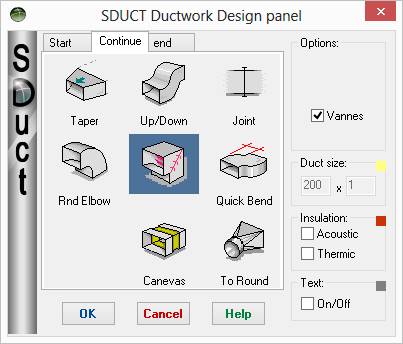
CONTINUING ROUND DUCTWORK
After you draw the initial round ductwork and you continue with Round Ductwork, you are presented with the following dialog box:
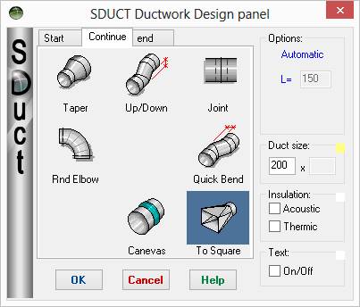
TAPER
This option allows you to transition from one ductsize to another, when you select this option the DuctSize box will become available so that you can indicate the new ductsize.
JOINT
This option allows you to show that two pieces of ductwork should be used with a joint, joining them together.
RND ELBOW
This option allows you to draw round elbows, please note that in this new version, it is not necessary to specify the angle of the elbow, this will be done while you are drawing the round elbows, which will be done in a loop that is ended when you right click or press Esc.
QUICK BEND
This option allows you to quickly create a bend to get around an odd angle.
BLANK OPTION
This option is outdated and will be removed in future versions/revisions.
CANEVAS
This option allows you to draw Flexible canevas Joint.
TO SQUARE
This option allows you to transition to square ductwork.
NOTE: While you are drawing ductwork, if you cross another piece of ductwork SDUCT will automatically make the existing ductwork appear to be underneath the ductwork that you just drew, unless you are holding down the ctrl key, then the ductwork that you just drew will appear to be under the existing ductwork.
ENDING ROUND DUCTWORK:
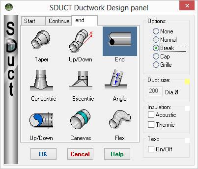
TAPER
This option allows you to transition from one ductsize to another, when you select this option the DuctSize box will become available so that you can indicate the new ductsize.
Up/Down (top middle)
This option allows you to indicate that there is a rise or drop in the duct elevation at this point, this does not show duct risers.
END
This option allows you start ductwork with various options:
· None
o This option allows you start with nothing at the end of a duct, this is very handy if you already have a duct riser that you just need to come off of the side of for example.
· Normal
o This option will show a line closing of the duct.
· Break
o This option adds in a breakline, so that you can show that the duct doesn’t stop but continues on. This is handy when you need to show that a duct goes under a piece of equipment, but showing it in hidden line form might get too confusing.
· Cap
o This option adds a cap to the end of the duct, this is handy if you need to make a tee fitting.
· Grille
o This option allows you to end the duct with a grille
CONCENTRIC
This option allows you to have a concentric take off from a piece of ductwork.
EXCENTRIC
This option allows for Side Take Offs
ANGLE
This option allows you to take off from ductwork in various (standard) angles.
UP/DOWN (BOTTOM LEFT OPTION)
This option allows you to create rises and drops in ductwork.
CANEVAS
This option allows you to draw Flexible canevas Joint.
FLEX
This option allows you to draw flex duct at the end of your ductwork.
NOTE: While you are drawing ductwork, if you cross another piece of ductwork SDUCT will automatically make the existing ductwork appear to be underneath the ductwork that you just drew, unless you are holding down the ctrl key, then the ductwork that you just drew will appear to be under the existing ductwork.
SQUARE DUCTWORK
When you begin square ductwork, you get the following Dialog Box:
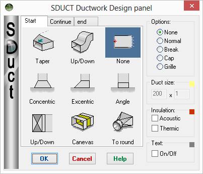
TAPER
This option allows you to transition from one ductsize to another, when you select this option the DuctSize box will become available so that you can indicate the new ductsize.
UP/DOWN (TOP MIDDLE)
This option allows you to indicate that there is a rise or drop in the duct elevation at this point, this does not show duct risers.
NONE
This option allows you start ductwork with various options:
· None
o This option allows you start with nothing at the end of a duct, this is very handy if you already have a duct riser that you just need to come off of the side of for example.
· Normal
o This option will show a line closing of the duct.
· Break
o This option adds in a breakline, so that you can show that the duct doesn’t stop but continues on. This is handy when you need to show that a duct goes under a piece of equipment, but showing it in hidden line form might get too confusing.
· Cap
o This option adds a cap to the end of the duct, this is handy if you need to make a tee fitting.
· Grille
o This option allows you to end the duct with a grille
CONCENTRIC
This option allows you to have a concentric take off from a piece of ductwork.
EXCENTRIC
This option allows for Side Take Offs
ANGLE
This option allows you to take off from ductwork in various (standard) angles.
UP/DOWN (BOTTOM LEFT OPTION)
This option allows you to create rises and drops in ductwork.
CANEVAS
This option allows you to draw Flexible canevas Joint.
TO ROUND
This option allows you to continue with round ductwork
NOTE: While you are drawing ductwork, if you cross another piece of ductwork SDUCT will automatically make the existing ductwork appear to be underneath the ductwork that you just drew, unless you are holding down the ctrl key, then the ductwork that you just drew will appear to be under the existing ductwork.
CONTINUE SQUARE DUCTWORK
When you continue with Square Ductwork, you get the following dialog box:
TAPER
This option allows you to transition from one ductsize to another, when you select this option the DuctSize box will become available so that you can indicate the new ductsize.
UP/DOWN
This option allows you to indicate that there is a rise or drop in the duct elevation at this point, this does not show duct risers.
JOINT
This option allows you to show that two pieces of ductwork should be used with a joint, joining them together.
RND ELBOW
This option allows you to draw round elbows, please note that in this new version, it is not necessary to specify the angle of the elbow, this will be done while you are drawing the round elbows, which will be done in a loop that is ended when you right click or press Esc.
If the Vannes box is check under options, then the elbows will have turning vanes.
SQR ELBOW
This option allows you to draw square elbows, like with the round elbows this enters into a loop so that you can draw multiple elbows at once, please note that you either have to right click or press escape to get out of the loop.
If the Vannes box is check under options, then the elbows will have turning vanes.
QUICK BEND
This option allows you to quickly create a bend to get around an odd angle
.
BLANK OPTION
This option is outdated and will be removed in future versions/revisions.
CANEVAS
This option allows you to draw Flexible canevas Joint.
TO SQUARE
This option allows you to transition to square ductwork.
NOTE: While you are drawing ductwork, if you cross another piece of ductwork SDUCT will automatically make the existing ductwork appear to be underneath the ductwork that you just drew, unless you are holding down the ctrl key, then the ductwork that you just drew will appear to be under the existing ductwork.
ENDING SQUARE DUCTWORK
When you go to end square ductwork, you get the following dialog box:
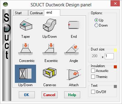
TAPER
This option allows you to transition from one ductsize to another, when you select this option the DuctSize box will become available so that you can indicate the new ductsize.
UP/DOWN (TOP MIDDLE)
This option allows you to indicate that there is a rise or drop in the duct elevation at this point, this does not show duct risers.
END
This option allows you start ductwork with various options:
· None
o This option allows you start with nothing at the end of a duct, this is very handy if you already have a duct riser that you just need to come off of the side of for example.
· Normal
o This option will show a line closing of the duct.
· Break
o This option adds in a breakline, so that you can show that the duct doesn’t stop but continues on. This is handy when you need to show that a duct goes under a piece of equipment, but showing it in hidden line form might get too confusing.
· Cap
o This option adds a cap to the end of the duct, this is handy if you need to make a tee fitting.
· Grille
o This option allows you to end the duct with a grille
CONCENTRIC
This option allows you to have a concentric take off from a piece of ductwork.
EXCENTRIC
This option allows for Side Take Offs
ANGLE
This option allows you to take off from ductwork in various (standard) angles.
UP/DOWN (BOTTOM LEFT OPTION)
This option allows you to create rises and drops in ductwork.
CANEVAS
This option allows you to draw Flexible canevas Joint.
ATTACH
This option allows you to attach the ductwork to a specific dimension size.
NOTE: While you are drawing ductwork, if you cross another piece of ductwork SDUCT will automatically make the existing ductwork appear to be underneath the ductwork that you just drew, unless you are holding down the ctrl key, then the ductwork that you just drew will appear to be under the existing ductwork.
During using SDUCT you will always know the current color Entities set in the SDUCT standard file.
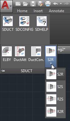
SDUCT v. 17.354 comes now with some popular Lisp tools.
TAPER
|
|
TAPER tool allow 4 command:
-TAPER Allows you to create Square to Square transition duct.
-R2S Allows you to make Round to Square transition duct.
-S2R Allows you to make Square to Round transition duct.
-R2R Allows you to make Round to Round transition duct.
In all cases, you need to enter the desired duct width then, select 2 parallel lines.
To alternate between flat end or center transition, you just have to move your mouse during the process and you will see the previous result dynamically.
Length of transition is calculated as follow (3 x ( ductsizeA – DuctSizeB))
And minimum length is adjusted at 150 If LUNITS variable is 2 and lower Or adjusted to 6 if LUNITS variable is 3 and higher
|
DUCTCONNECT
|
|
DUCTCONNECT
This lisp tool allows you to start a new duct conduit from existing one.
Command: DUCTCONNECT
First Select between Square or Round duct type: Duct Type (S)quare/(R)ound <S>:
Then enter your duct size width Duct Width:
Then select a line of any existing duct and move your mouse to place the new duct conduit.
You will see a little start at your selected point meaning that takeoff will switch automatically direction when moving the mouse. (see gif)
Length of takeoff connection is adjusted at 150 If LUNITS variable is 2 and lower Or adjusted to 6 if LUNITS variable is 3 and higher
|
DUCTATTACH
|
|
DUCTATTACH
This lisp tool will help you to join 2 parallel lines to an existing duct conduit.
You will see dynamic preview while moving the mouse.
To switch connection type, hit the TAB key on your keyboard.
Length of takeoff connection is adjusted at 150 If LUNITS variable is 2 and lower Or adjusted to 6 if LUNITS variable is 3 and higher.
|
ELBY
|
|
ELBY
This simple Lisp is a HUGE TIME SAVER !
Connect two double line Duct conduit with an elbow with only 2 mouse click !
The first mouse click must be the interior elbow gore and the second the exterior.
Windows selection must cross 4 lines to work properly. (see gif)
Drawing elbows was never been so easy ! |
These tools are now part of the SDUCT installation can also be downloaded separately for free from our site at:
www.ductisoft.com\freelisp.html
Simply load the VLX files from the SDUCT installation folder with the “_APPLOAD” command.
Otherwise, SDUCT will load the required LISP via the SDUCT menu.
SDUCT
Commanf to draw double-line DuctWork.
SDCONFIG
Configuration panel of SDUCT allowing user to configure Client Standards.
SDUNDERCOLOR
New Command allowing user to set the color when duct appear UNDER another.
SDMLEADER
Command allowing user to use MLEADER
SDDIMLDRBLK
Command allowing user to use default Leader Block
SDUCTHELP
This command will open the actual Help file.
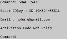
Command allowing user to activate the SDUCT license.
Example :
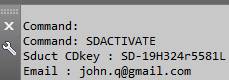
With success activation, you must see this dialog box:
Otherwise:
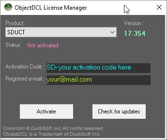
You can also use the ObjectDCL software activation tool.
By using ODCLLICMAN you will see the installed DuctiSoft programs.
Select SDUCT and activate your license.
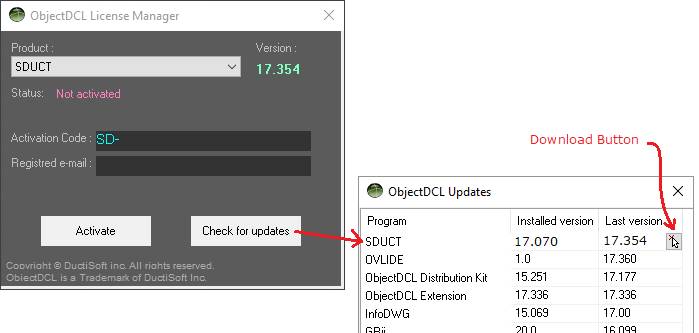
Feel free to check the new version of your product and download it directly.
NOTE: The SDUCT CDkey can be used only for one user only. However, this activation can be transferred to another computer as often you need.
KNOWN BUGS
- The clear dimension check box doesn’t always work as expected.
Programmers:
- Andrea Andreetti, President DuctiSoft inc.
- Chris Wade, CAD Manager BREEN Engineering inc.
Special thanks go to Mr. Chris Wade, CAD Manager from BREEN Engineering inc., for his knowledge and time dedicated to improving SDUCT.

Copyright © DuctiSOFT inc. All rights reserved.
SDUCT User Guide
DuctiSOFT inc. distributes this publication with software that includes an end user agreement and is furnished under license and may be used only in accordance with the terms in the license agreement. The content is this publication is protected under copyright law.
This publication may not be modified or reproduced in any form or derivative manner for any purpose.
The content of this guide is furnished for informational use only and is subject to change without notice. DuctiSOFT inc. assumes no responsibility or liability for any errors or inaccuracies that may appear in the informational content contained in this guide.
DuctiSOFT inc. reserves the right to revise and improve its products as it sees fit. This publication describes the state of this product at the time of its publication, and may not reflect product at all times in the future.
In no event shall DuctiSOFT inc. be liable to any person or entity with respect to any loss or damage that is incidental or consequential in relation to the instructions in this publication or by the computer software and hardware products described in this guide.
DuctiSOFT and SDUCT are trademarks of DuctiSOFT inc. in the United States, Canada, and other countries.
All other brands or products are trademarks or registered trademarks or their respective holders.
All specifications are subject to change without notice.